Flowbench Project.
Click on the the pictures for a higher resolution picture in a new browser.
The bench with the valve board out;
This picture shows the valve bases which have threaded plates on the bottom. The end result is the valve handles do not go up and down with the valves.
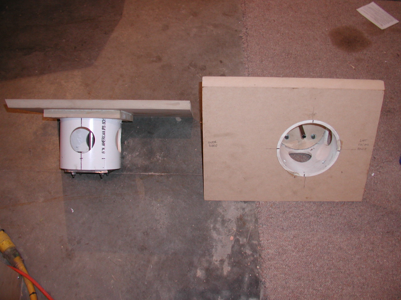
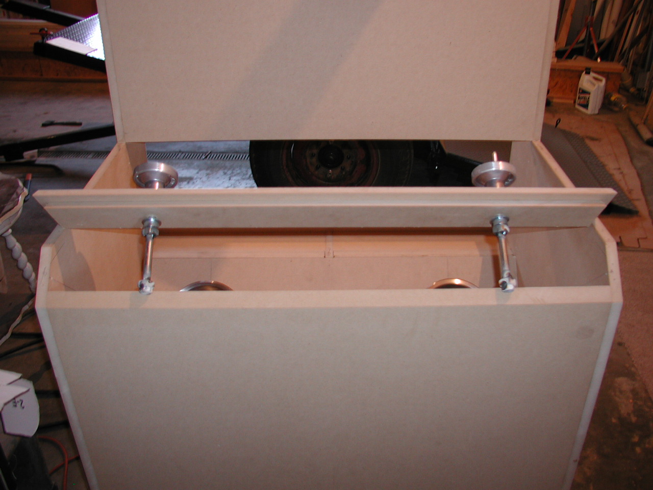
This picture shows the valve baseplate assemblies in place.
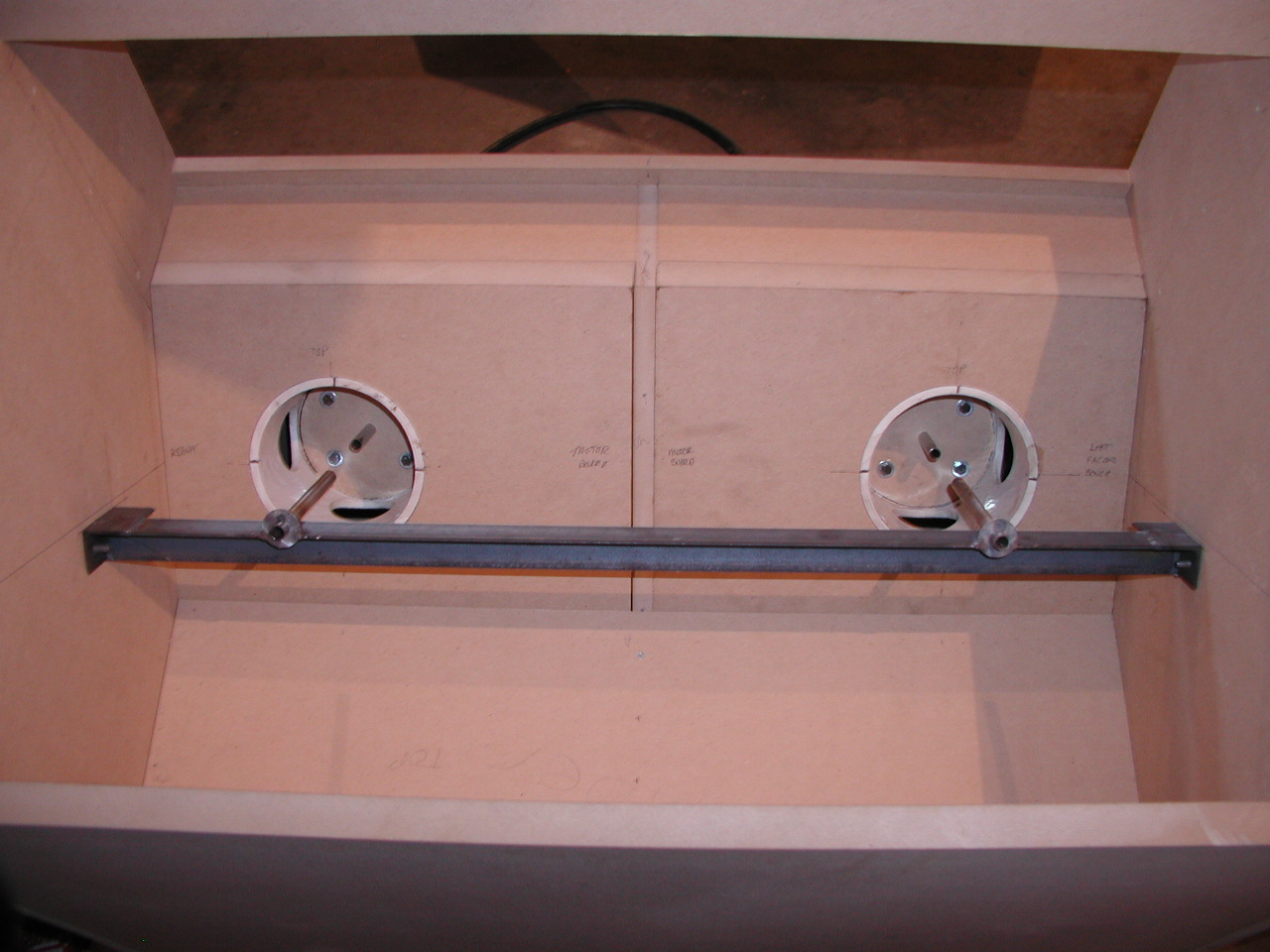
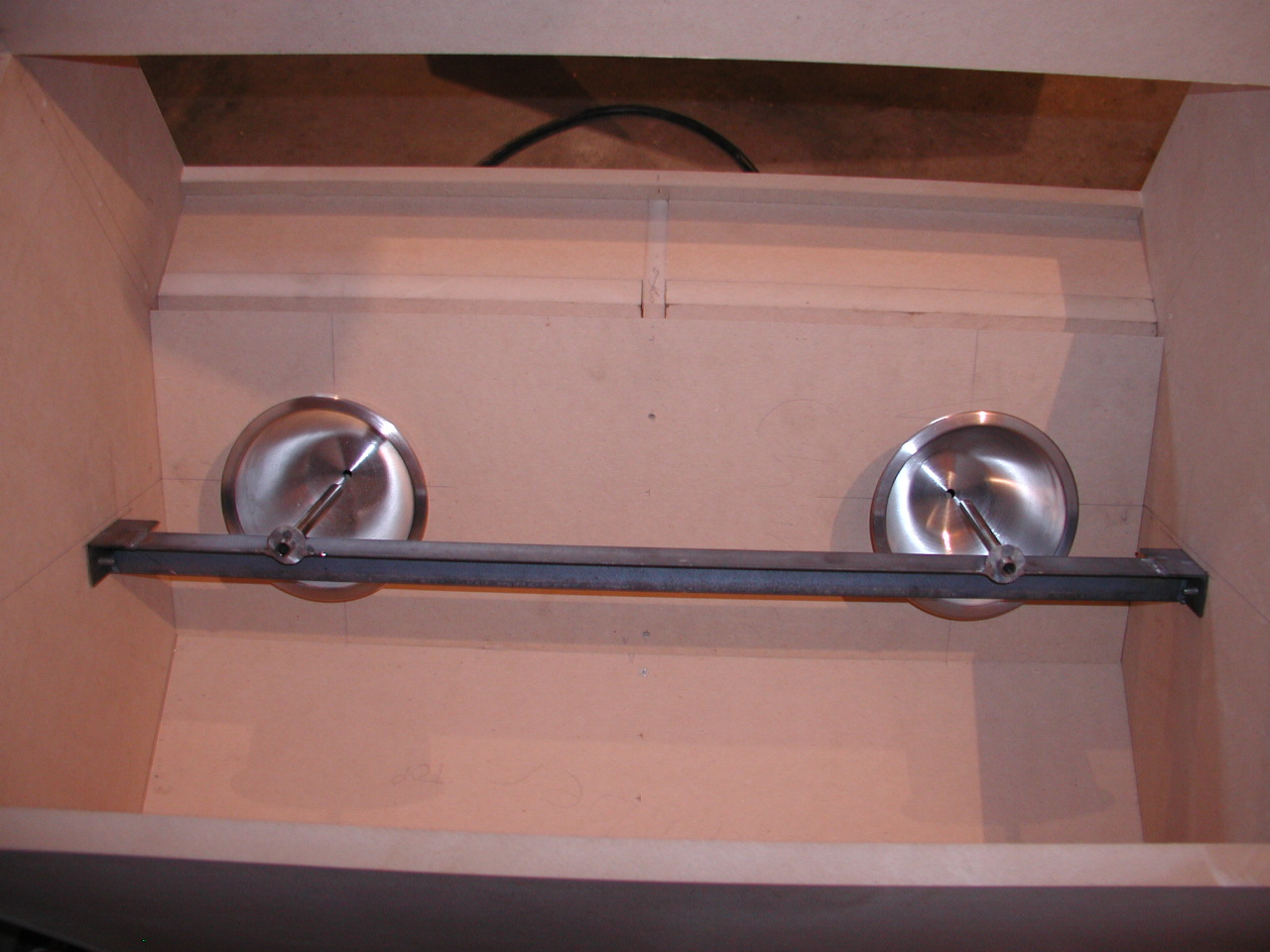
This picture shows main valve seat board in place;
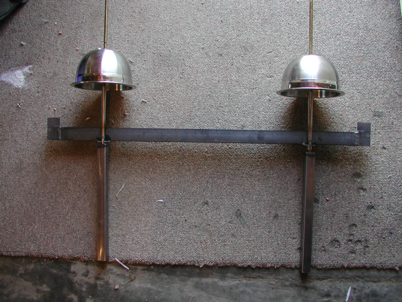
The "valves" in place;
The valve actuators with square nut drive. The 1/2 valve actuator bolts rotate in brass bushings in the valve actuator mount board;
The threaded rods the "valves" are bolted on. 3/8" fine thread brass with a square nut drive.
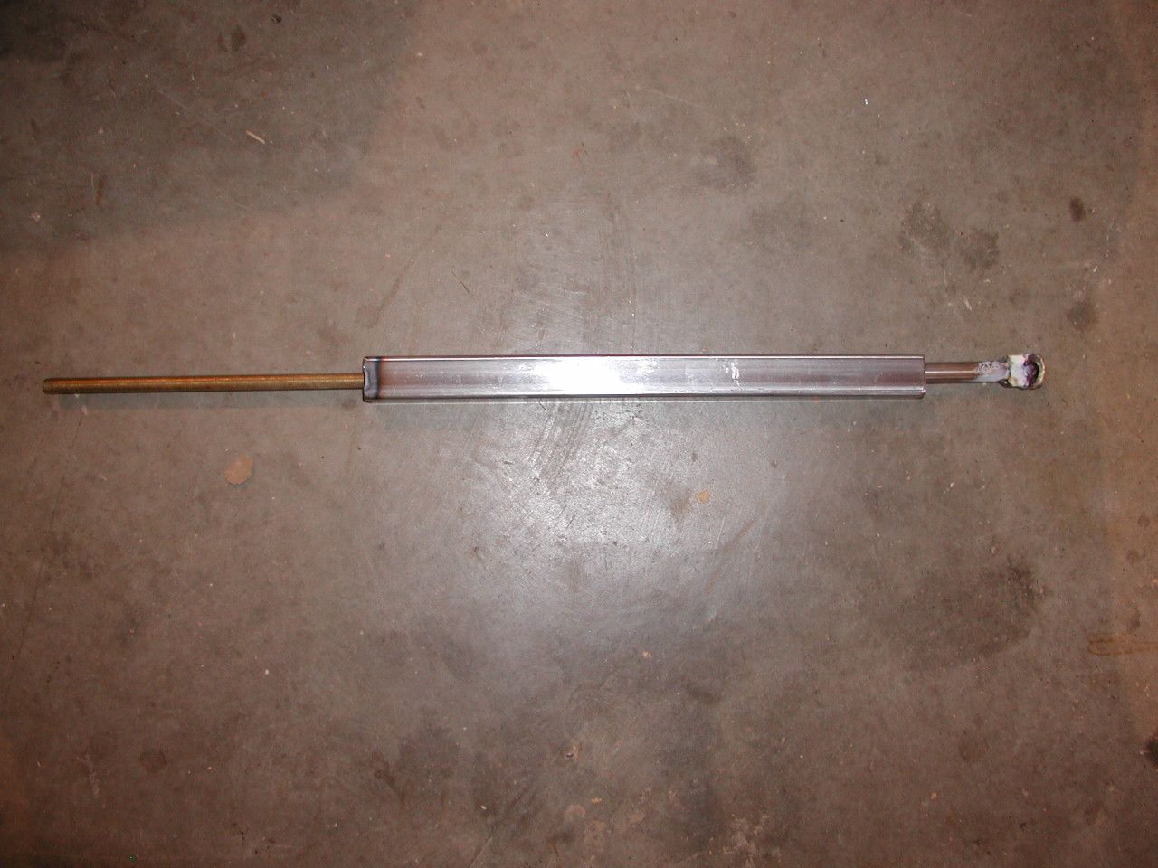
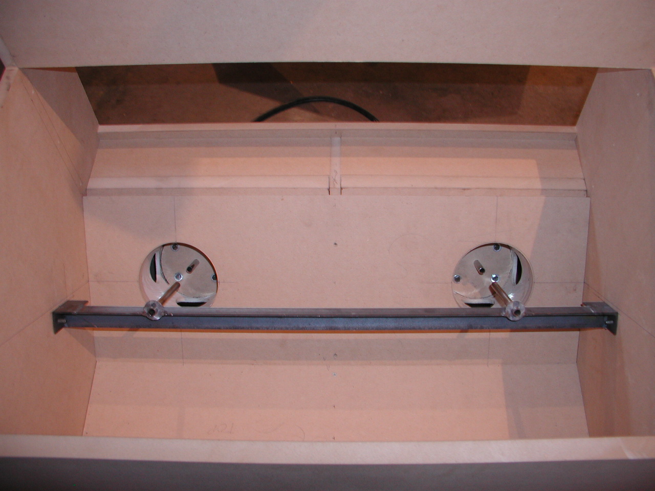
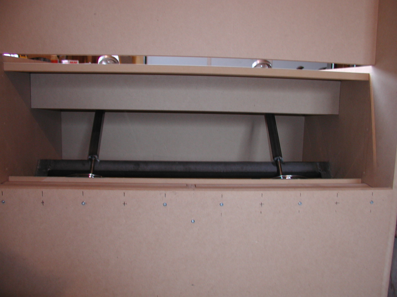
The threaded rod/valve assembly on the upper rod guide bar. You can see the threaded rod will slide up and down in the square tube.
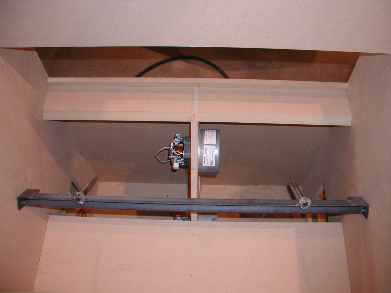
The rod guide bar and rod/valve assembly in the bench;
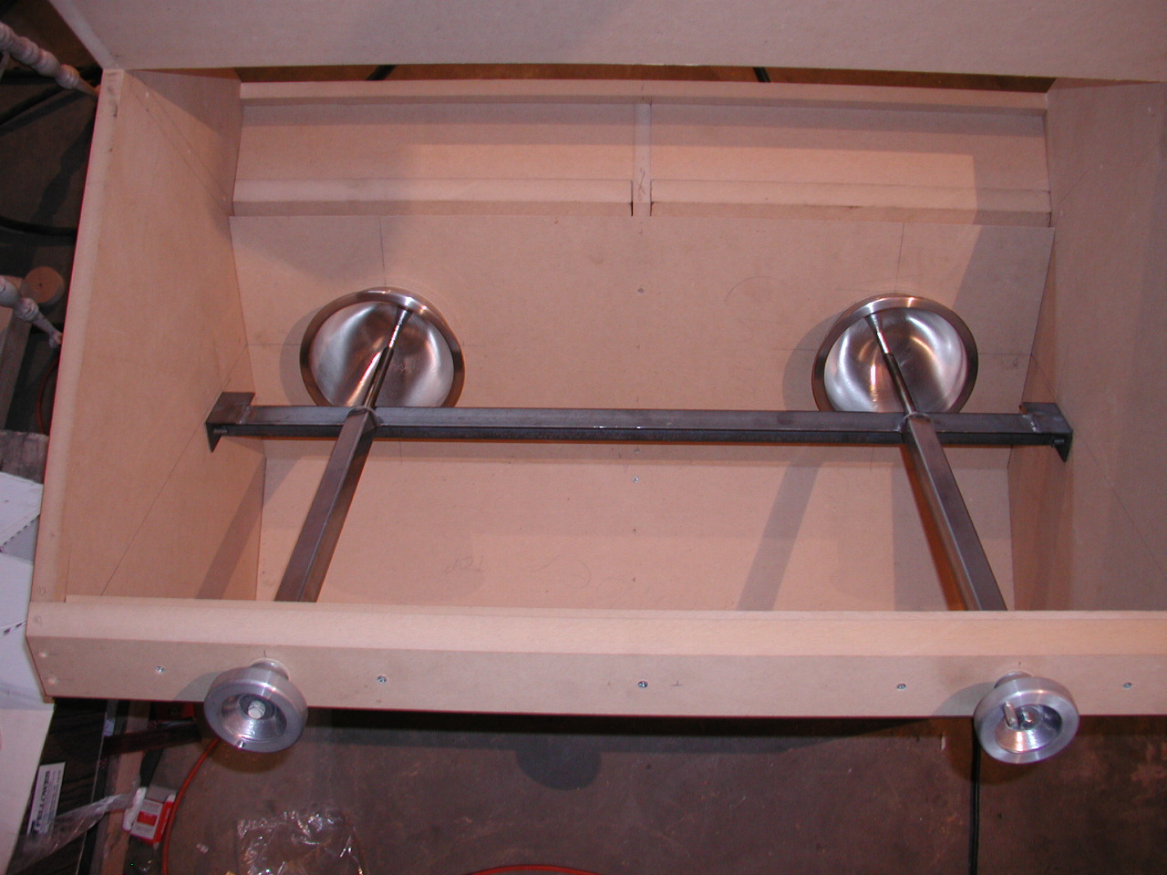
View from the back of the bench. You can see the 4" x 1 1/2" bench top brace, and that I am using two layers on the top of the bench. There are a few places I'm doubling up the MDF for strength.
All pictures and text on this entire site are the property of RevSearch and may not be copied and/or used in any way without the specific permission of RevSearch.
Back
to the RevSearch home page.
RevSearch ©11-14-2005 JL