Flowbench Project page 2.
Click on the the pictures for a higher resolution picture in a new browser.
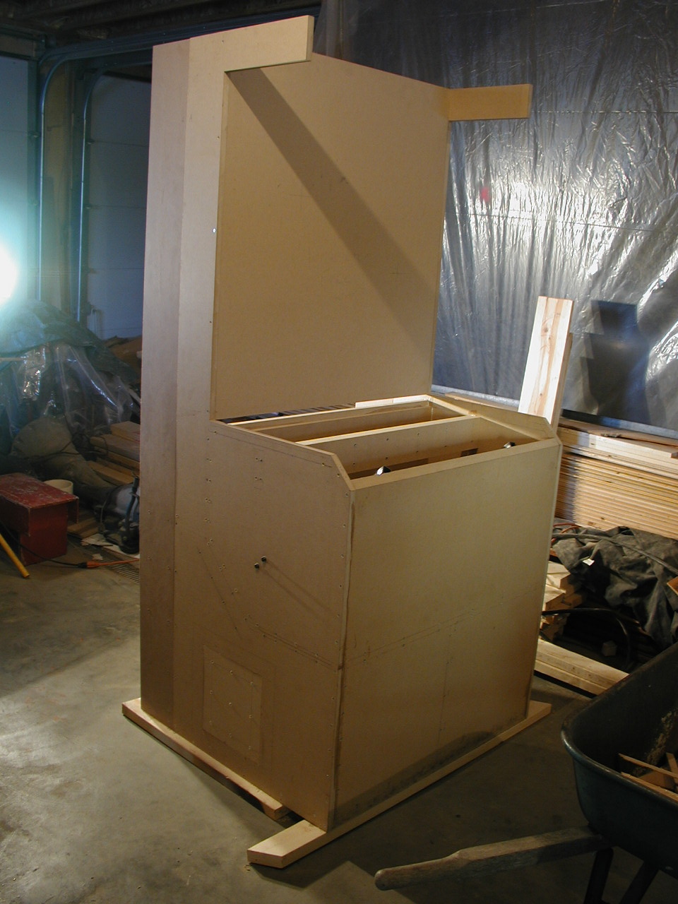
I decided to add 7" depth to the back of the bench. This will allow three more motors, more depth behind the manometer panel for the flow element, and a removable back modification. As you can see I plugged the side holes.
Here is another view of the back. I took advantage of the depth addition to double up the floor and motor chamber side panels. I have two more layers to add to the top back of the motor chamber. You can see how the Gorilla glue expands. I need to buy ANOTHER sheet of MDF.
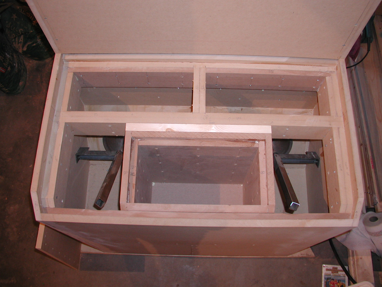
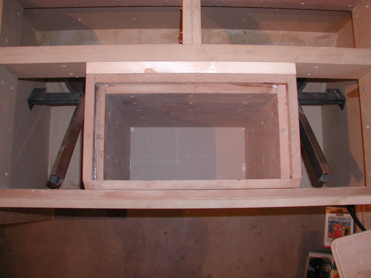
Here are two views of the test fixture feed box. It will be fed through a hole in the bottom and piping coming from the pitot section through the pressure side of the motor chamber.
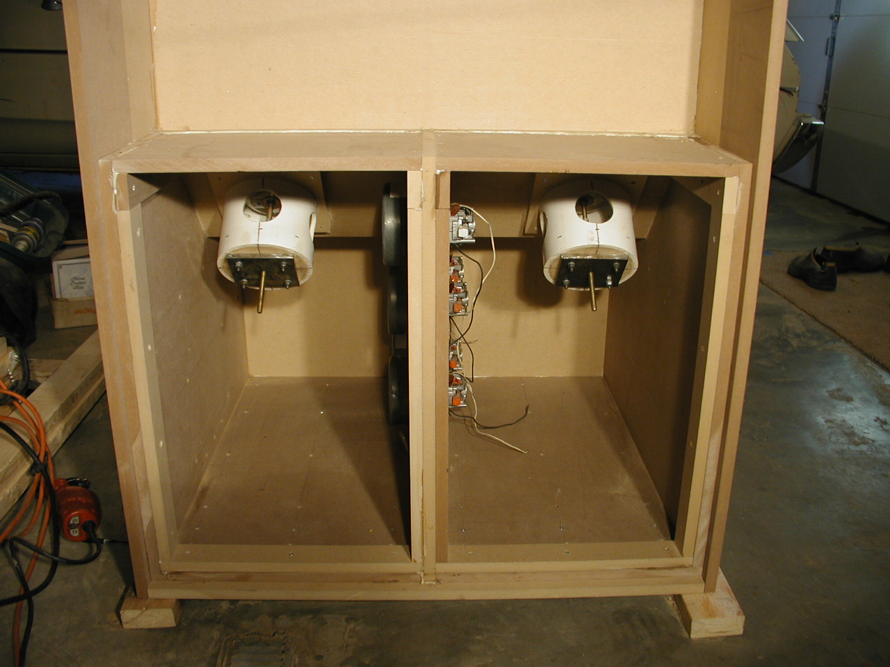
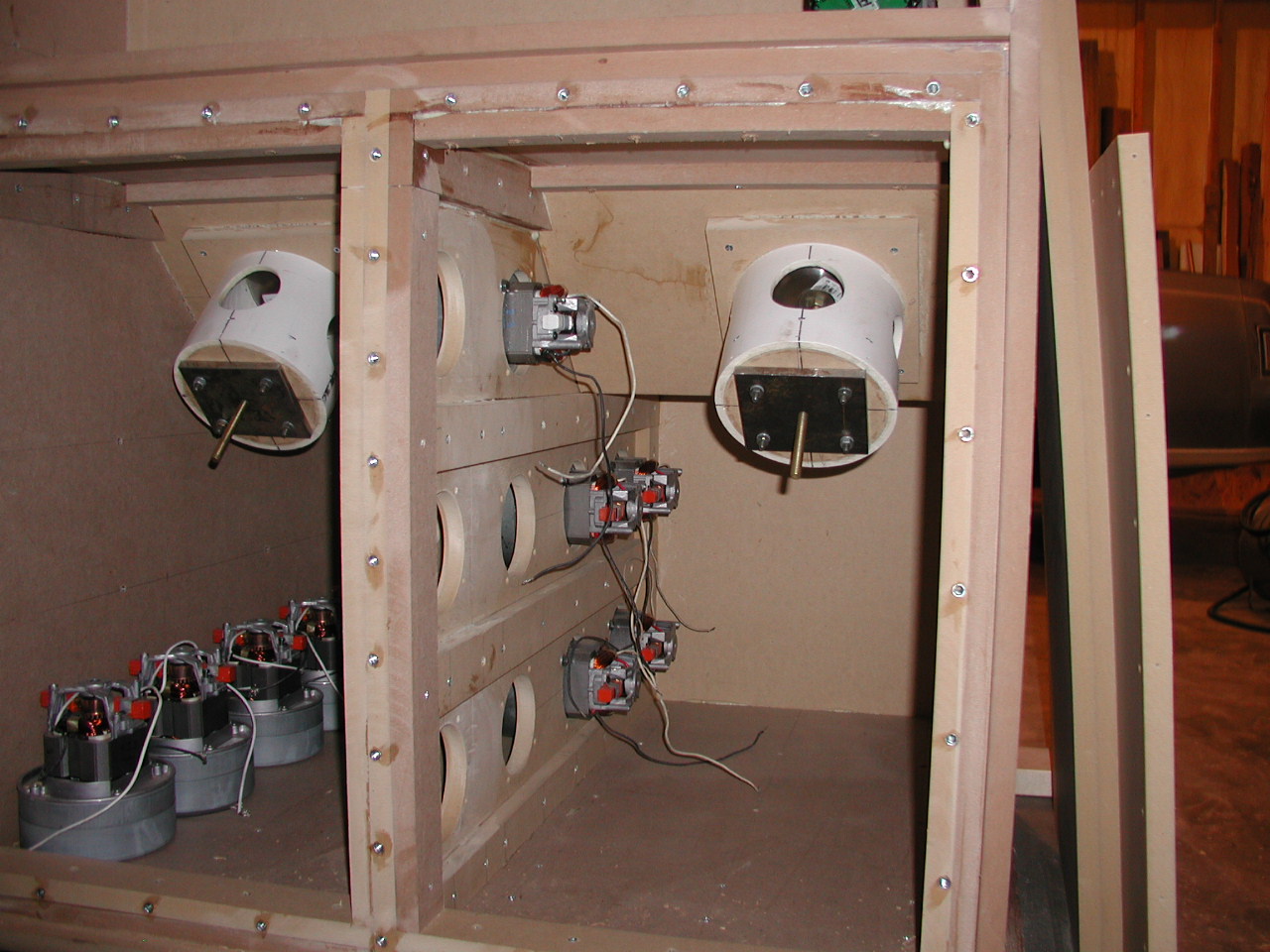
The motor chamber;
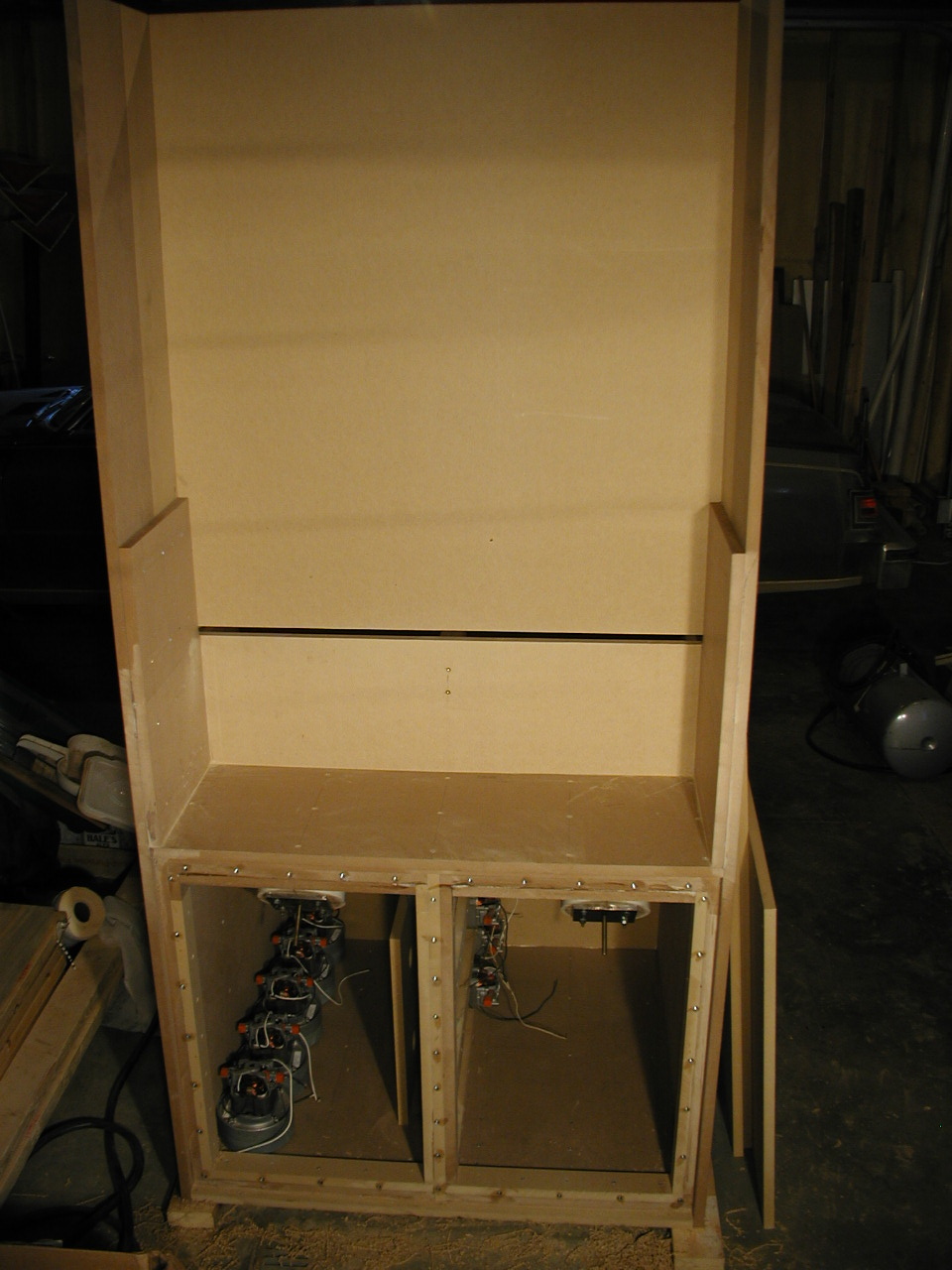
The back of the bench;
The back of the bench with the proposed piping layout. I plan to come out of the valve chamber with two 3" pipes, combine them into one on the top of the bench and feed the 2.5" or 3" pitot flow section. There is enough vertical height for at least 60" of straight piping with the pitot in the middle. The bottom pitot section will connect to a larger 4" or 6" u pipe feeding the test fixture feed box (located in the valve chamber). The flow will reverse through the piping for intake and exhaust testing.

All pictures and text on this entire site are the property of RevSearch and may not be copied and/or used in any way without the specific permission of RevSearch.
RevSearch home page.
RevSearch ©11-14-2005 JL