Flowbench Project page 3.
Click on the the pictures for a higher resolution picture in a new browser.
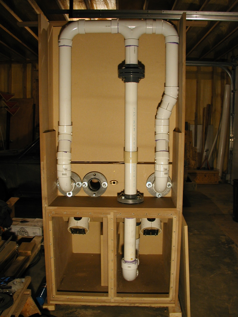
The piping layout. There is 65" length of 3" flow element piping between the T at the top and the 4" elbow, this means there will be 32" on either side of the pitot. The pitot element will be placed where the coupling is positioned on the middle vertical section. All the piping ends into the various fittings were cut 45 degrees for smooth id. The flange sockets had the stop lip cut out so the piping itself butts up, again for a smooth id. The piping doesn't butt up right at the flange joint, it butts up 1/4" into one of the paired flanges so the joint is "indexed" together. The open 3" flange is for a future Flow Performance PWM valve for automatic test pressure control.
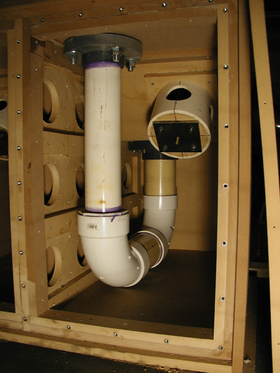
This view shows the 3" piping leading into the 4" which connects to the test fixture feed box.
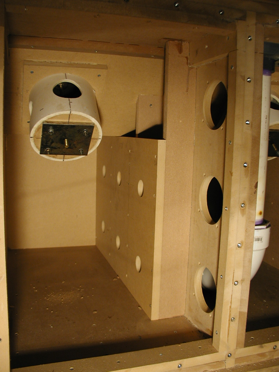
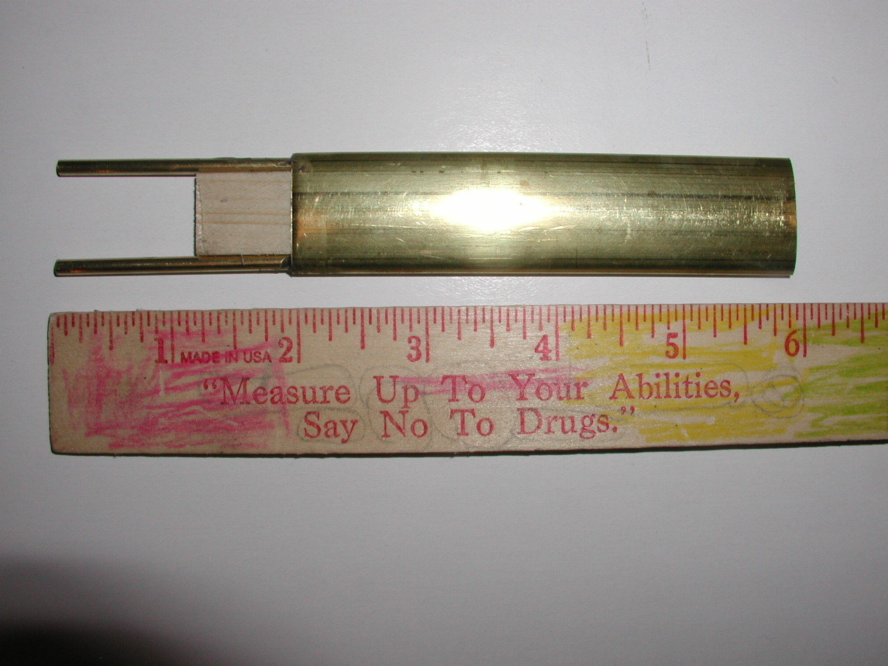
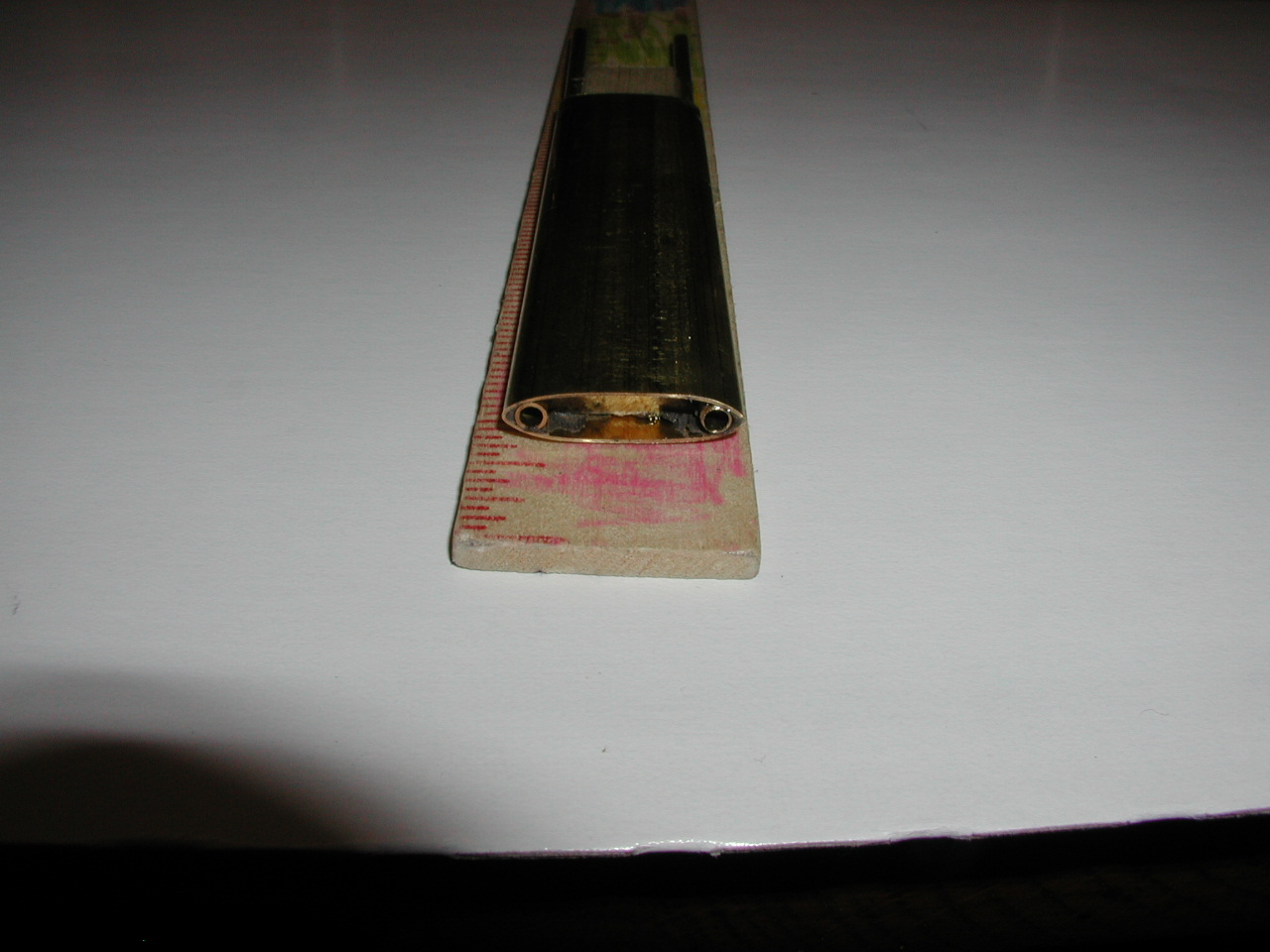
This is the motor suction side, there will be four motors open and three pairs of two with some sort of check valves on the suction side of the motor. Right now I'm thinking aobut 2" sump pump check valves on PVC pipe stubs coming out of the motor suction board you see in this photo. The start of bi-directional averaging elliptical pitot tubes.
All pictures and text on this entire site are the property of RevSearch and may not be copied and/or used in any way without the specific permission of RevSearch.
Back
to the RevSearch home page.
RevSearch ©11-14-2005 JL